Application of Piezo Technology in Holographic Storage

With the development of society and the progress of technology, people's demand for information keeps increasing. Due to the multi-media of information, people's data processing is no longer simple text, sound, image, but digital multimedia information integrated by high definition and high quality sound and motion image. The requirement of information data storage is higher and higher, especially the requirement of storage size and rate, which promotes the development of various storage technologies. Existing memory technologies, such as magnetic storage and semiconductor storage, are still improving to meet the demands of large capacity and high access rates, but these storage methods are gradually approaching their physical limits. Holographic storage will be a more ideal storage technology. Holographic optical storage technology is a kind of information storage technology with great development potential, which has attracted more and more attention because of its advantages such as high information redundancy, high storage capacity and high access rate.

Holographic Storage Technology

Holographic storage is an ultra-high density storage technology that uses light interference to record information in the form of holography on the recording material and recover the stored information in the form of diffraction under specific conditions.

The principle of holographic recording is the same as that of holography, but the specific method is different. One is that, the data is stored not on film but in a material that reflects light. A piece of medium like the size of a small sugar cube contains thousands of pages, each containing millions of bits of information. Second, the way of using object light is different.

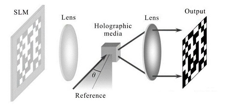
During the write operation of holographic storage, the output of a laser beam is divided into two beams, one of which is expanded and then projected on the recording medium as a reference light. After the other laser beam is expanded, it is reflected by the surface of the recorded object, and as the object light, it is also projected onto the recording medium. The object light is used to carry the data, which is expanded to be able to fully illuminate the entire stereo light modulator (SLM). The SLM is similar to an LCD panel, which displays the binary data to be stored in an array of light and dark pixels in a full-page fashion. After the object light passes through the SLM, some light up and some dim, which is to carry the data of the page. Then, the same reference light acts in the medium, turning the whole page of data into an interference fringe pattern, and the whole page of data is stored in the medium through the interference pattern.

Note: picture source network

When reading data, an image of the bright and dark pixels (denoted as ones and zeros) that were originally written in is returned to the reading array of a CCD (charge Coupled device) by shining a reference light on the storage medium and diffusing its internal interference pattern. The entire page of data can then be read.

Note: picture source network

Characteristics of Holographic Storage

(1)High storage density and large capacity. The high storage density is obtained by recording multiple holograms in the same area of the photosensitive material. At present, the most commonly used multiple recording methods are multi-wavelength, multi-angle and multi-phase recording. In order to obtain higher storage density, several multiple recording methods can be integrated.

(2)High data transmission speed and short access time. Holograms are stored and read in a page-wide manner, where all information bits on a page are recorded and read in parallel. In addition, the holographic database can be addressed by inertia-free beam deflection or wavelength selection, not necessarily by the electromechanical read-write head required in disk and optical disk storage, so the data transmission rate and access rate can be further improved.

(3)High redundancy. Different from bit-by-bit disks and discs, holograms store information in a distributed way. Each bit of information is stored on the entire surface or volume of the hologram, so local defects and damage of the recording medium will not cause information loss.

(4)High storage reliability. Holographic storage materials are silver salt crystals, organic polymer or metal compound crystals with good optical properties and stable chemical properties. Even if the storage carrier is partially damaged, the data can still be read, and the information recorded by the holographic storage material can be kept for more than 30 years.

Coaxial Holographic Disc Data Storage System


We have introduced so much information about holographic storage, what is the role of piezo technology in holographic storage?


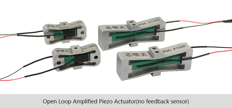
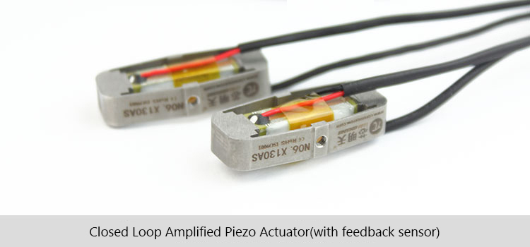
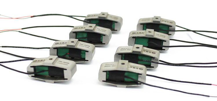
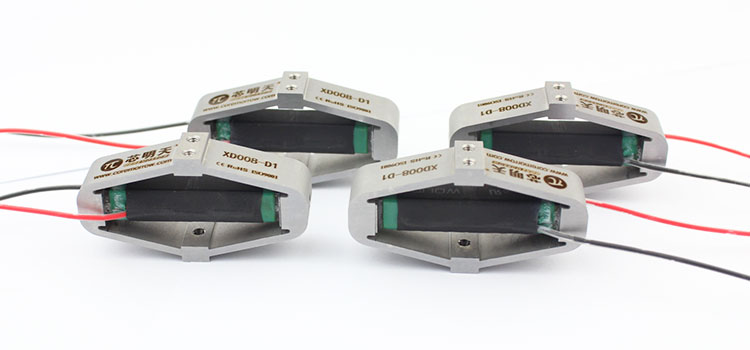
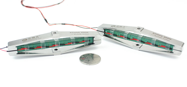
CoreMorrow Piezo Products

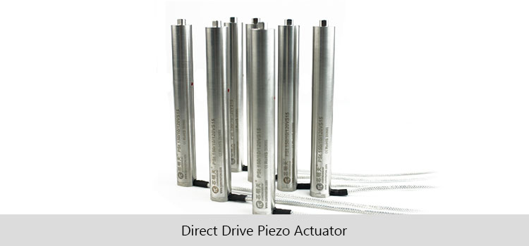
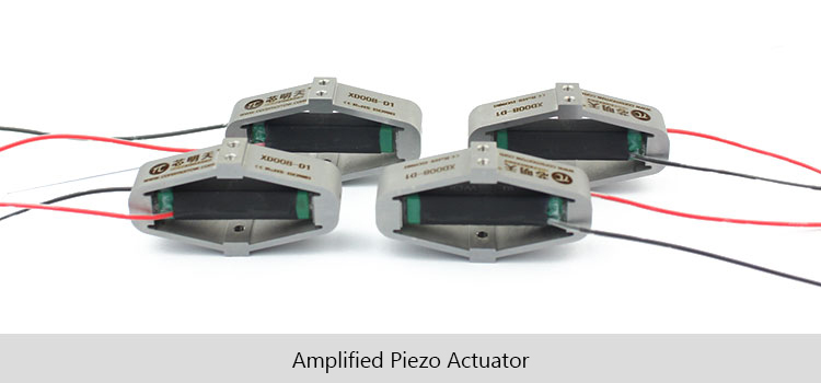
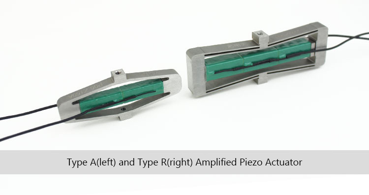
CoreMorrow piezo technology is a kind of micro motion control technology based on PZT inverse piezoelectric effect. Its ultra-high precision position control and ultra-fast adjustment response provide fast and high-precision optical path control for holographic optical storage technology.

There are many kinds of piezo products based on piezo technology, which can be linear motion or angular motion. At the same time, it is also a combination of linear motion and angular motion.

  1. Piezo Objective Scanner Products

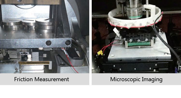
CoreMorrow piezo objective scanner products are specifically designed for carrying the objective lens to do nanometer linear step movement so as to achieve the microscopic and focusing purpose. It can realize a microscopic lens linear precision position control with precision up to nm level, load capacity 500g, movement range 1mm, and the response time is only a few milliseconds.

The piezo objective scanner is connected to the objective lens through an adapter to quickly lock the objective lens into the desired position. A variety of threaded teeth are available, such as M27×0.75, M26×0.75, M26×1/36", M25×0.75, W0.8×1/36", etc., and can also be customized for easy integration and installation with the microscope. It can match Zeiss, Nikon, Olympus, Leica and other standard lenses. It can also be used in combination with a manual control table via an adapter.

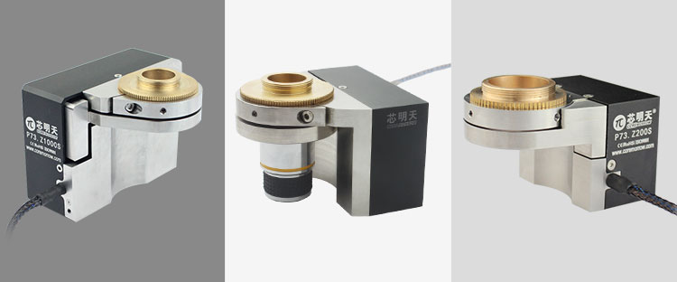
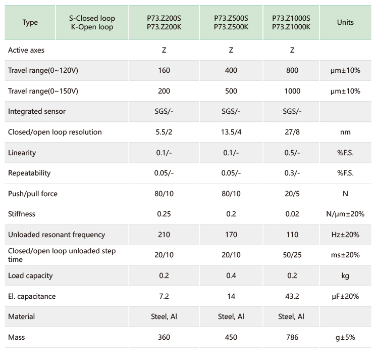
P73 Series Piezo Objective Scanner
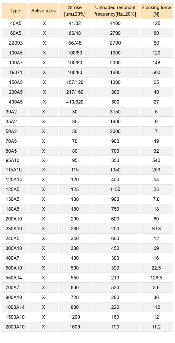
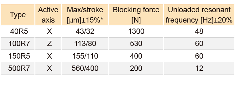
Technical Data

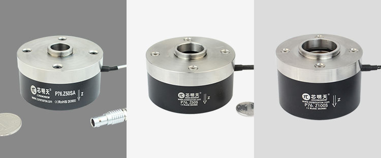
P76 Series Piezo Objective Scanner

Technical Data

  1. CoreMorrow Piezo Tip/Tilt Stage

Piezo tip tilt stage is drived by piezo actuator, with internal non-return difference flexible hinge parallel guide structure design, and the external mechanical structure achieves uniaxial or multi-axial angular tilt motion through the expansion of internal piezo actuator, its small amount of compensation ensures that the deflection mirror with high accuracy and stability of movement. The built-in high precision sensors for closed-loop control, achieves sub-micro radian resolution and micro radian positioning accuracy.

Piezo tip tilt stage can realize the high-precision real-time steering adjustment of the optical path, which can generate θx, θy axis deflection, and optional linear axis, used to drive the reflection/transmission lens to deflect and change the path direction of the reflection/transmission optical path. The deflection range of CoreMorrow tip tilt stage is up to 43mrad, and the bearing capacity is up to φ110mm lens. It has nrad accuracy and response times up to milliseconds.

P33 Tip/Tilt Stage

Technical Data

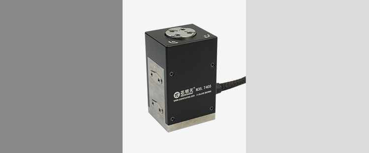
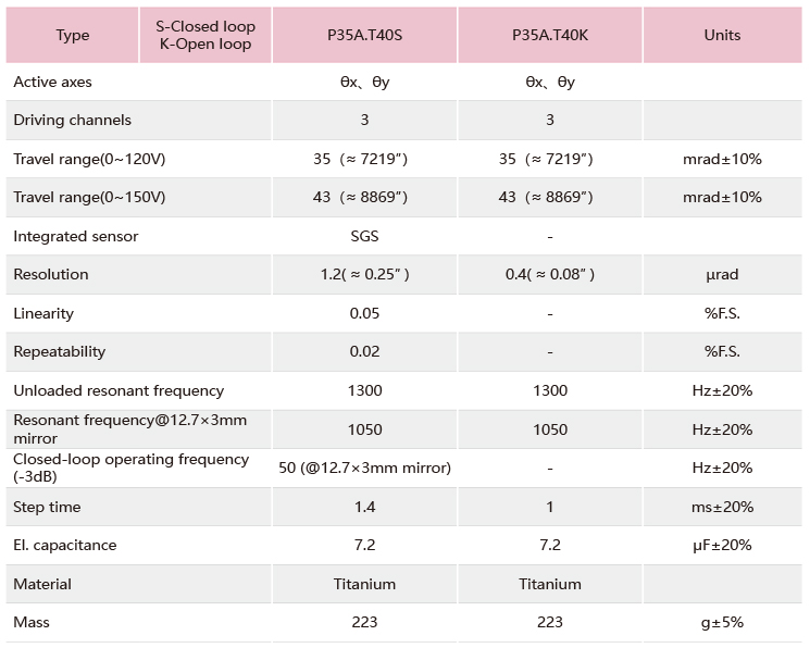
P35A Piezo Tip/Tilt Platform

Technical Data

CoreMorrow Nano Motion-Amplified Piezo Actuator

The name of amplified piezo actuator is derived from the combination of its driving source, structural principle and function. "Piezo" refers to its driving source, that is, using piezo actuator to generate motion; The "Amplified" is to realize the displacement amplification of piezo actuator through the flexible hinge guiding mechanism. "Actuator" is its function, its moving end can produce actuation to carry the object and adjust the micro displacement.

The amplified piezo actuator is equipped with a mechanical fixed mounting interface, which can be directly connected with the external load or the mounting surface through threads. It can also drive the external mechanical structure, which in turn completes the motion regulation.

Amplified Piezo Actuator VS Direct Drive Piezo Actuator


Type of Amplified Piezo Actuator

Amplified piezo actuators can be divided into two series according to the motion direction: type A (contraction) and type R (expansion). Typically, the displacement of the amplified actuator of type A begins to contract when the actuator is powered on, while the displacement of the type R  begins to elongate when the actuator is powered on. If the lower end is fixed and used as Z direction, the amplified actuator of type A will produce downward displacement while type R upward.

Depending on the sensor configuration, the amplified actuator can be divided into open-loop (no positioning feedback sensor) and closed-loop (integrated positioning feedback sensor) versions. In open-loop mode, the resolution of piezo actuator is infinitely high, which is limited only by the noise of the control device. However, due to the hysteresis and creep characteristics of piezo actuator, its displacement repetition accuracy and displacement stabilization accuracy are low. However, the closed-loop version of the piezo actuator eliminates hysteresis and creep. Meanwhile, the closed-loop version can form a closed-loop control through the CoreMorrow piezo controller, which can read and track the displacement value and make adjustment in time.

Introduction of Amplified Piezo Actuator

The amplified piezo actuator is an actuator that amplifies the displacement generated by preloaded low pressure piezo ceramics by mechanical amplifying structure. The mechanical magnification structure is an oval mechanical shell, which is made of steel. It not only provides optimized preloading force for piezo stacks, but also plays a protective role for the stacked ceramics, so that they are not subjected to tension. Excessive tension will cause irreversible or even fatal damage to piezo stacks. The elliptic mechanical magnification structure also provides the user with an easily integrated mechanical interface.

Basic Structure of Amplified Piezo Actuator

The basic structure of the amplified piezo actuator is shown in the figure below, integrated with piezo ceramics inside and metal flexible hinges outside. It has mobile ends up and down with threaded holes, which can be used for its own installation and load installation.

Motion Principle of Amplified Piezo Actuator

The piezo stacks produce deformation displacement along the main axis, that is, the long axis direction, and the elliptical mechanical structure amplifies the displacement along the short axis direction, which means, the amplified piezo actuator amplifies the transverse elongation displacement of the piezo ceramic to the axial displacement output by the mechanism amplification principle. The elliptic shell is divided into inner elliptic structure (type R) and outer elliptic structure (type A). The displacement directions are X-direction expansion and X-direction contraction, respectively.

Amplified Piezo Actuators

Compact Amplified Piezo Actuator

80N Blocking Force

66μm Displacement

2700Hz Unloaded Resonant Frequency

Custom Type A Amplified Piezo Actuator

100μm Displacement

150N Blocking Force

2000Hz Unloaded Resonant Frequency

Type R Compact Amplified Piezo Actuator

41μm Displacement

125N Blocking Force

4100Hz Unloaded Resonant Frequency

Type A Amplified Piezo Actuator with Large Blocking Force

540N Blocking Force

95μm Displacement

350Hz Unloaded Resonant Frequency

Amplified Piezo Actuator with Large Displacement

25N Blocking Force

400μm Displacement

370Hz Unloaded Resonant Frequency


Parameters for Amplified Piezo Actuator

Type A (Outer Ellipse)

Type R (Inner Ellipse)

Applications

The amplified piezo actuator are often used for optical switching, optical alignment and other applications due to the small size, large displacement and fast response. In addition, the application range of the amplified piezo actuator is very wide, as shown in the following examples of applications.

  • Optics

Probe scanning, optical lens positioning, optical switch, shutter/shutter stabilization, micro-scanning, wafer testing, astronomy, focus positioning, laser cavity tuning, optical fiber coupling and deformation, FBG (fiber Bragg grating) deformation, chopper, interferometer, PDP crystal cutting, modulator, etc.

  • Mechanics

Fiber stretching, tool positioning, pick and place tools, diamond turning, elliptical piston processing, damping, dynamic control, new generation ultrasonic or sonic vibration, NDT, instrument fatigue monitoring, etc.

  • Fluidics

Proportional valves, pumps, flow measurement technology, inkjet technology, syringes, droplet generators, etc.

Application Cases

Installation and operating instructions

  • Safety guide

The amplified piezo actuator is designed with advanced technology and safety standards. For your own safety and the correct use of the product, please pay attention to the following points. Temperature changes and pressure will charge the piezo actuator, and the piezo actuator will remain charged for a period of time when disconnected from the controller, so please note:

  • Do not disassemble the actuator without permission;
  • Discharge the actuator before installation, by connecting it to the controller;
  • Do not remove the controller during operation;
  • Before use, check whether the connecting cable is intact and whether the product and controller are effectively grounded. During operation, strictly regulate the operation. After powering on the product, do not touch the product with your hands (the maximum voltage is more than 150V) to avoid danger.

In order to prevent damage to the product caused by improper operation, please pay attention to

the following points:

  • The amplified actuator should be used in dust-free, oil-free and lubricant-free environment;
  • The load should not exceed the bearing capacity of the product. Pay attention to the torque when loading. Do not pry or twist the hinge of the load surface to avoid damage to the structure;
  • In the event of any exception, please close the relevant part immediately;
  • The recommended voltage for long-term use is 0 ~ 120V;
  • Do not disassemble the product to avoid damage;
  • Do not stretch or bend the cable connector to prevent damage;
  • Connect the piezo actuator and controller with the cable provided by CoreMorrow;
  • Do not use cable extension cord, if you need longer cable please contact our sales.

2) Installation and Precautions

Before installation, check whether the connection cable is damaged or broken, and whether the drive power is grounded.

The installation steps of the amplified piezo actuator are as follows:

  • Clean the installation platform before installation;
  • Connect load, which should not exceed the bearing capacity of the actuator;
  • Install the amplified piezo actuator on the measuring platform or fix it on the measuring platform through the optical platform conversion seat. Please select the appropriate bolt for  installation according to the diagram.
  • Connect the product connection cable to the controller.

In order to prevent the amplified piezo actuator from being damaged, please pay attention to the following points:

  • Do not use beyond the voltage range specified in the data sheet;
  • Do not drop the piezo ceramic to avoid any form of mechanical impact;
  • A preloaded piezo actuator can withstand some tension (not caused by the contraction of the piezo actuator) but not shear, torque, or bending moments. These conditions may cause damage to the piezo ceramic inside the actuator.